Your work on the assignment can be simplified if you use the guide you have read. You can find more samples if you visit our blog. The number of examples is large, so you can find a sample for almost any discipline. If you feel that you can’t deal with your homework on your own, you can get assignment help on assignmentshark.com. You just need to place an order with your requirements and set the deadline. Even if your assignment seems too difficult for you, our expert can deal with it easily. You can select an expert on your own according to the bids, ratings, and sphere of knowledge. We will meet your “do my homework free” request with ease, but free will be only expert’s advice.
We strived to create a service that can meet all customers’ expectations, and we are glad to state that many customers remain satisfied after using our service. The reason is that our experts follow all customer requirements and can complete high-quality tasks. Moreover, your personal information will be secure and never passed to third parties.
Pendulum Wave Effect in MapleSim Example
Task: Demonstrate the step-by-step creation and subsequent simulation of a pendulum wave effect in MapleSim.
Solution:
This guide will illustrate the effect known as the pendulum wave effect. It is based on using 11 pendulums of varying lengths and setting them up next to each other in a line in such a way that the longest makes 51 oscillations in a minute, with each subsequent one making more, up to 61 oscillations. This results in an effect of the pendulums alternating into various patterns and, after a certain time, returning to their initial positions forming a line. The main focus of this example will be the use of custom equations, parameter blocks, shared subsystems, and customized geometry.
We start very similarly to the previous example by using a fixed frame, a revolute joint, and a rigid body, with the only difference being using only one rigid body frame. (We do not need to link two pendulums, so one rigid body frame suffices.) We group the rigid body and the rigid body frame part into a subsystem and, by right-clicking, convert it into a shared subsystem. Doing this allows the subsystem to be linked with the copies created from it and changes made to any of these links to reflect in all of the subsystems. With the basic design set, we can start the parameterization process. For our pendulum wave effect, we will require two system wide variables to define the time needed to complete one cycle of pendulum patterns, and amplitude. This can be achieved by using a parameter block from the model workspace toolbar and setting the parameters inside the block as follows:
- theta = -1/3 Pi, representing the amplitude
- cycle = 30, representing the cycle time in seconds
To set up the parameterization for the links themselves, we need two more variables. One of them will be used to control the number of oscillations of each separate pendulum and is, therefore, dependent on the time of one cycle, and the other one will control the movement of the pendulums via their lengths based on oscillations and amplitude. To define it, we will use the following equation:
- T= (1/(number of ocsillations))*cycle
- L = 0.25*T2 /(1+0.625-1*theta2 )
We use the created amplitude parameter theta in the initial conditions of our revolute joint as the starting angle and set it to strictly enforce initial conditions, and the created length parameter L to set the x-offset of the rigid body frame in our shared subsystem. After copying the pendulum model 10 times and setting up the oscillations on each one, we are able to generate the result shown on Figure 1. Now we can focus on making the visualization more appealing.
Figure 1: Pendulum wave effect model
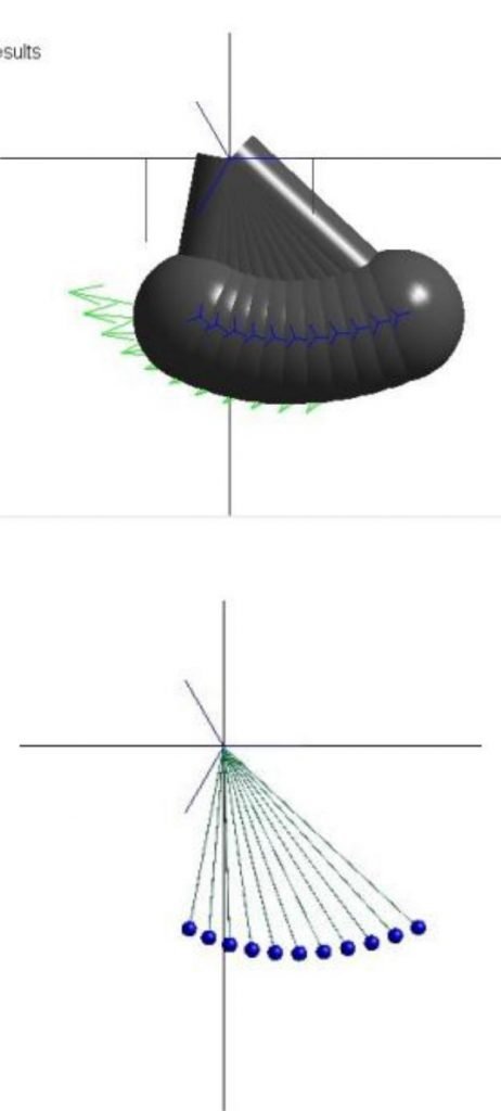
In the visualization window, we can observe that the implicit geometry offered by MapleSim is sometimes very dense, and because of this, it is difficult to observe the behavior of the model. We will correct this with the use of custom geometry on the rigid body frame and rigid body components located in any of the subsystems, since we defined them to be shared, and as such, the geometry changes will propagate into every single one. We will use a cylindrical geometry for the arms of the pendulums and spherical geometry for the weights, setting their values as follows:
- the radius of the cylindrical geometry to 0.001
- the radius of the spherical geometry to 0.01
Lastly, the implicit geometry of MapleSim has to be turned off from the visualization window toolbar, and now our pendulum wave effect model with customized geometry is finalized.
Figure 2: Pendulum wave effect model with implicit geometry (top) and customized geometry (bottom)


