Task: demonstrate the step-by-step creation and subsequent simulation of a double pendulum in MapleSim.
Solution:
For this example, we will need the following components from the multibody library:
-
- the fixed frame component
- the rigid body frame component
- the revolute joint component
- the rigid body component
The fixed frame component will represent a set point in the scene, on which the pendulum will hang. We use two rigid body frames to represent the arms on each of the separate pendulums and a rigid body that serves as the weight on the pendulum. The revolute joint is used to allow rotational motion. We place all of these components in the model workspace by dragging them from the palettes pane and connecting their ports as shown on Figure 1, creating a simple pendulum that is ready to be simulated for better grasp on how our model behaves (Figure 2).
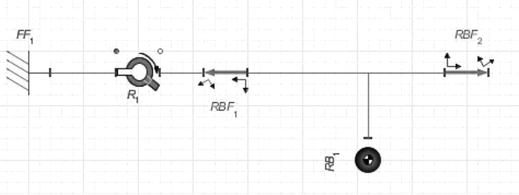
Figure 1: Model of a simple pendulum
Since our goal is to create a double pendulum and not a simple pendulum, we set the x-offset of the first rigid body frame (RBF1) to -1.5 and the x-offset of the other rigid body frame (RBF2) to 1.5, which results in the rigid body moving to the middle of the pendulum.
For convenience, we can group the rigid body frames and the rigid body components forming the link to the second pendulum into a subsystem. To do this, we select the components and press Ctrl + G or select Edit → Create Subsystem from the main menu.
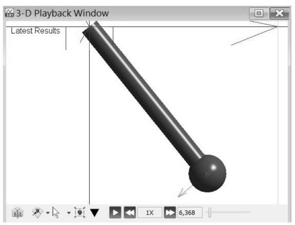
Figure 2: 3D visualization of a simple pendulum
In order to edit the subsystem, we double-click it and add a port to the right side of the subsystem, because otherwise it would be impossible to add further connections to the system. This is done by clicking on the port 31 of our RBF2 and linking it to the border of the subsystem (Figure 3). As this subsystem has no parameters, we use the parameters mode on the navigation toolbar while in the subsystem to set up its parameterization.
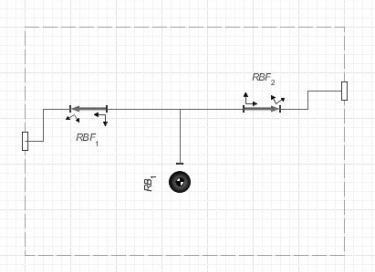
Figure 3: Pendulum link created as a subsystem
We create the following parameters: m = 5 kg, representing the weight of the pendulum link, l = 1.5 m, representing the length of the link, and I = 0.05 kg*m2, representing the inertia of the link. We replace the corresponding values in the x-offset part of our rigid body frames and mass and inertia values in our rigid body and with that being done, our subsystem is fully parameterized (the reason for this will be explained later). To finish producing our double pendulum model, it is only necessary to select our created subsystem and revolute joint, copy them, and connect the second revolute joint to the first pendulum (Figure 4).
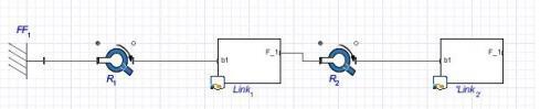
Figure 4: Fully modelled double pendulum
Another useful addition to our model, and the reason for parameterizing the subsystems, are probes. With the chaotic movement of our double pendulum, it is reasonable to add probes that monitor the acceleration or speed of our separate pendulums. Firstly, however, the creation of a parameter set, storing our currently used 32 values for variables, will allow us to roll back any changes we might perform while testing different initial conditions.
This is done by clicking Edit → Store Parameter Set from the main menu and our created set will appear in the project tab of the palettes pane. We add two probes to the scene using Attach Probe, connecting each one to a separate rigid body within our subsystems. Ticking the acceleration and speed checkboxes enables the monitoring of the corresponding variables. After running the simulation again, the results are shown in the visualization window (Figure 5).
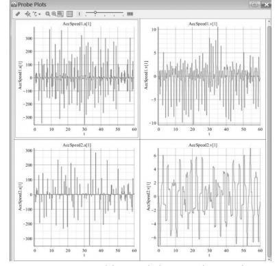
Figure 5: Double pendulum probe results
Since there is the parameter set we created earlier, it is possible to compare the behavior of our model with different parameter settings or initial conditions. For example, Figure 6 depicts a comparison of double pendulums with varying lengths.

Figure 6: Comparison of different model settings
In the guide that you have read, you can find ideas to deal with your own assignment. If you need more help with your homework, you first need to place an order on AssignmentShark.com. We are always available, so you can contact us 24/7. If you use our service, you can be sure that your personal information will be secure and never passed to third parties. Our experts can deal with assignments of any type. To get a good grade, it’s enough to place an order on our site and wait a bit for help. You can select the most suitable writer for your order on your own.
In the case when you are assigned a task, immediately leave it to our team of experts on AssignmentShark.com. As soon as our expert gets your order, he or she will start to work on it. Our service is used to save time that students usually don’t have. To do this, just tell us what you need to do and we will help you. Don’t hesitate to get our assignment help right now!