Task: Gain basic knowledge of how to work with Ansys Fluent module by example from the problem shown below.
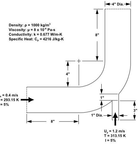
The problem is shown schematically in the figure below. A cold fluid at 293.15 K flows into the pipe through a large inlet and mixes with a warmer fluid at 313.15 K that enters through a smaller inlet located at the elbow. The mixing elbow configuration is encountered in piping systems in power plants and process industries. It is often important to predict the flow field and temperature field in the area of the mixing region in order to properly design the junction.
Solution:
(Part 3)
- Close ANSYS Design Modeler by selecting:
File → Close Design Modeler or by clicking the ‘X’ icon in the upper right-hand corner.
ANSYS Workbench automatically saves the geometry and updates the Project Schematic accordingly.
- View the list of files generated by workbench by selecting:
View → Files
Meshing the Geometry
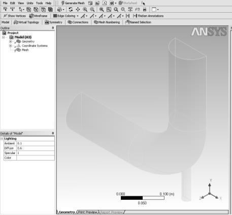
- Open the ANSYS Meshing application. In the ANSYS Workbench Project Schematic, double-click the Mesh cell in the elbow fluid flow analysis system. This displays the ANSYS Meshing application with the elbow geometry already loaded. You can also right-click the Mesh cell to display the context menu where you can select the edit.
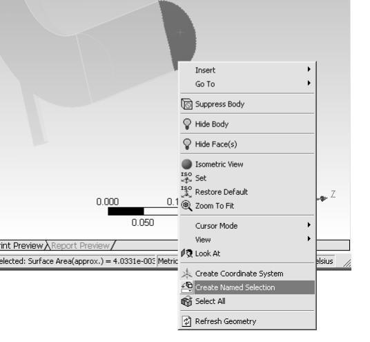
- Create named selections for the geometry boundaries. In order to simplify your work later on in FLUENT, you should label each boundary in the geometry by creating named selections for the pipe inlets, the outlet, and the symmetry surface. Select the large inlet in the geometry that is displayed in the ANSYS Meshing application.
Right-click and select the Create Named Selection option. This displays the Selection Name dialog box.
- In the Selection Name dialog box, enter “velocity-inlet-large” for the name and click OK. Perform the same operations for:
The small inlet (“velocity-inlet-small”);
The large outlet (“pressure-outlet”);
- The symmetry planes (“symmetry”).
- Set some basic meshing parameters for the ANSYS Meshing application.
- Expand the Sizing node by clicking the “+” sign to the left of the word “Sizing” to reveal additional sizing parameters.
- Add a Body Sizing control.
- Click the new Body Sizing control in the Outline tree.
- Enter “6e-3” for Element Size.
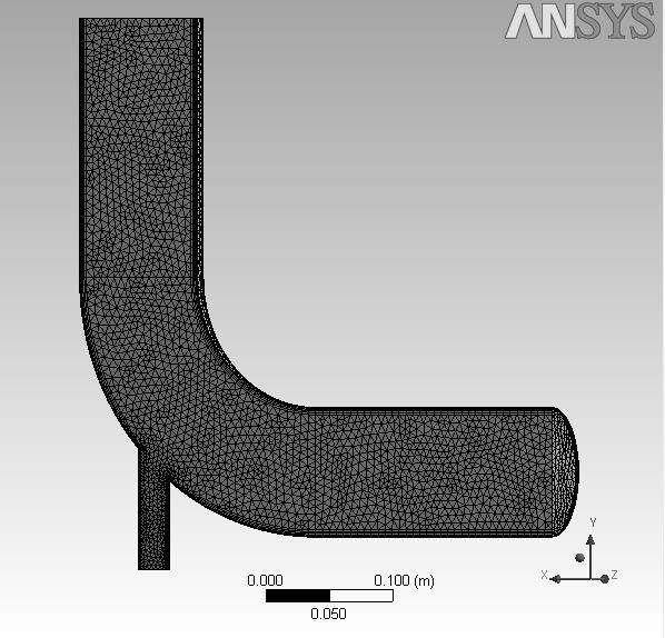
- Generate the mesh.
- Close the ANSYS Meshing application.
- View the list of files generated by ANSYS Workbench.
You can close the ANSYS Meshing application without saving it because ANSYS Workbench automatically saves the mesh and updates the project schematic accordingly. The Refresh Required icon in the Mesh cell has been replaced by a check mark, indicating that there is a mesh now associated with the fluid flow analysis system.
The sample presented can help you to start working on your own assignment. Your work can be created much easier and faster if you use our guide as a template. The next step after reading through the guide is to handle your assignment. However, if you feel that you can’t deal with your task on your own, get help on assignmentshark.com. Here you can get help from experts in different fields of knowledge. Note that when you have an assignment to do, but don’t have enough time, you can get our help. To access our assistance, place an order with your requirements and set the deadline.
On the site, you can select the expert who will be the most suitable one for your order. We work 24/7 so you can always receive help when you need it. After successful cooperation with our expert, you can leave your feedback on our site. This will help us to improve our service and offer new options of work to our customers.