Double Pipe Heat Exchanger Using ANSYS Workbench
In order to design a Double Pipe Heat Exchanger in ANSYS 16.1 the next steps were
accomplished:
a) Creating the project:
- Open the ANSYS 16.1 workbench;
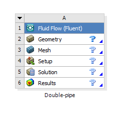
- Select Fluid Flow (Fluent) in the toolbox menu at the left area of the window and create a new project.
- Rename the Project on “double-pipe” as shown in the Figure 1 below.

Figure 1. Project “double-pipe”
- Save the project
b) Creating Geometry:
- Open the DesignModeler by double-clicking the Geometry button.
- Select the YZPlane in the Tree Outline and select ‘Look At’.
- Create New Sketch by pushing the button on the Plane/Sketch toolbar.
- Repeat step 3 four times.
- Select Sketch1. Switch to the sketching mode from Modeling mode and in settings select
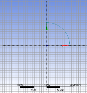
Grid ‘Show in 2D’ ‘Snap’. Select the Major Grid Spacing to be 1 m, and Minor-Steps per Major to be 10. - Create an Arc by Center by clicking the origin and then the Y axis to select the start of the arc, and then the Z axis to show the end (see figure 2).

Figure 2. Sketch 1 ‘Arc’
- Create a close quarter by drawing two lines from to edges of the arc to the origin.
- Select the dimensions of the arc by clicking ‘Dimensions’ ‘Radius’. Select the value of R1 to be 0.3 m.
- Click the Modeling tab.
- Select Sketch 2 – Sketching Tab.
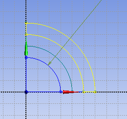
- Select the Arc by Center in order to create two arcs like at the Sketch 1. connect edges of two arcs accordingly.
- Repeat step 11 for Sketch 3 and 4 (see the Figure 3 below).

Figure 3. Sketches of the arcs
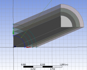
- Extrude the Sketch 1 with the Depth of 10 meters. Click Generate.
- Extrude the Sketch 2, where the Operation should be changed to Add Frozen in Details View. The Depth should be equal to 10 m as well.
- Repeat Step 14 for all Sketches. (see Figure 4 below)
Figure 4. Extruded section of the double-pipe
- Select each part in a body-tree and change the names and solid/fluid on: ‘Inner-Fluid’, fluid; ‘Inner_pipe’, solid; ‘Outer_fluid’, fluid; ‘Outer_pipe’, solid accordingly.
- Select all four bodies, and Form New Part by right-clicking on them.
- Close DesignModeler and Save in Workbench.
c) Generation of the mesh:
- Double click Mesh in the Project Schematic.
- Select the YZOplane view.
- Select the Cursor Mode to Face.
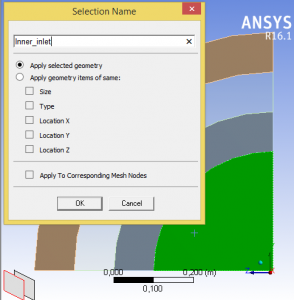
- Select Create Named Section with the name ‘Inner_inlet’ on the innermost section of the detail. (see the Figure 5 below).

Figure 5.
- Repeat the operation for the third section (name it ‘Outer_inlet’).
- At the opposite side of the detail repeat the previous steps but enter the names: ‘Inner_outlet’ and ‘Outer_outlet’ accordingly.
- Select the outer surface of the pipe and select Create Named Section with the name “insulation_surface”.
- Select all four surfaces of the pipe and click Create Named Section and enter symmetry_1.
- Repeat the operation for the other side of the pipe with the name “Symmetry_2”.
- Select Mesh by clicking on it. Change the Relevance Center from Coarse to medium.
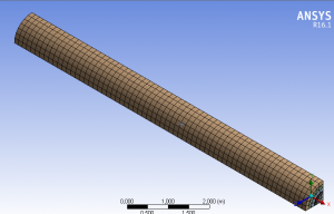
Click ‘Update’ button. (see result in the Figure 6 below). Close the Mesh window and Save the project.
Figure 6. Mesh
Fluent Setup:
- Click Setup;
- Select Models, Energy On, Viscous, k-Epsilon, Radiation, Discrete ordinates (DO).
Setup materials:
- Select Materials;
- Click Fluent Database;
- Select Water-liquid.
This assignment is an example of engineering problem solving created by our academic professionals. You are not allowed to use the information provided above without proper acknowledgments. Place your order, specify the instructions and wait for one of our specialists to write the assignment for you. Engineering problem solving is really hard, unless you cooperate with AssignmentShark professionals to get top-quality solutions for a fair price. Read our blog for more useful advice and secret tips, or leave your request and get professional assignment help online. Your grades will skyrocket once you decide to work with is!

