Assignments during your engineering classes may be sometimes hard, which is why we are here to share with you our knowledge and help you with your homework. One of our writers has picked the topic connected with cantilever beam analysis using Ansys Workbench and created a step-by-step guide to describe the right solution. All samples that you can find on our website are totally free and written by our expert writers.
When you have too many assignments to do, it’s no surprise that you can get depressed and totally exhausted. Each project requires an individual approach, a high level of attentiveness, and critical thinking skills. If you can’t manage a cantilever beam analysis even after reading our guide, it’s time to ask an expert for help with assignments. If you care about good grades and being always on time with your assignments, AssignmentShark.com is the best option for you! Our experts specialize in various disciplines: engineering, finance homework help, accounting, IT/web, physics, and more. If you won’t find the needed discipline in our order form, just mention your discipline in the extended form and we will find the required specialist for you. Your order will be completed with the highest attention and delivered on the specified time.
A Stress Analysis of a Cantilevered Beam
Task: using Ansys Workbench to perform a stress analysis of a cantilevered beam after constraining it and loading it with a 500 lb load. The beam is 4 inches long and has a 1-inch square cross-section.
Solution: this guide will show in steps what needs to be done to get to the final result.
Creating a new FLUENT project
1. Launch the program.
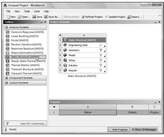
2. Start a new Static Structural analysis project. Once the Static Structural System appears, double-click on Geometry to start a new Design Modeler session. Select Inch as the unit system.
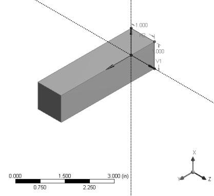
3. On the XZ Plane, draw a 1 by 1 square section.
4. Create a beam by extruding the section 4 inches in the Y direction. After, click Generate.
5. Save the project. Click on the Save icon, browse to a desired location and save the file.
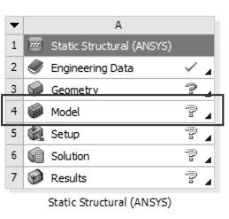
6. Begin a simulation using the solid model of the beam. In the Project Schematic area double-click on Model.
7. Check the bottom right portion of the Simulation window to make sure the units are set correctly.
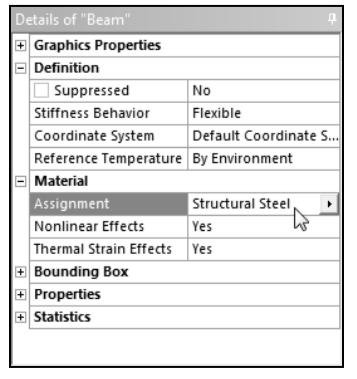
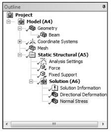
8. Set the material type. By default, the Simulation application sets all materials in the model to be Structural Steel. In this step we simply check that the material type has been set. Select Beam in the Outline pane and look at the Material setting in the Details pane below.
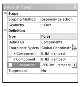
9. Set the load. The loading for this analysis consists of a 500 lb force in the Z direction. Select the Static Structural folder in the Outline view. The Environment toolbar is displayed. Orient the beam by rotating it so that the Z axis is in the vertical direction and one end of the beam is visible as shown. The Y axis should point towards you. Change the selection mode to Face by clicking on the face icon in the graphics toolbar and then select the visible end face. Click on Loads in the toolbar and select Force from the menu. In the Details pane, change Define By to Components if it is not already set. Enter -500 for the Z component and 0 for the X and Y components.
10. Set the boundary conditions. The boundary condition for this analysis consists of a fixed support at one end of the beam. Orient the beam by rotating it so that the Z axis is in the vertical direction and the opposite end of the beam is visible. The Y axis will point away from you. Select the visible end face of the beam. Select the Static Structural folder. Click on Supports in the toolbar and select Fixed Support. Click on Apply in the Details window pane.
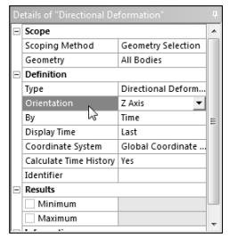
11. Request results. Select the Solution folder. In the toolbar change the selection filter to Body and click on the beam to select it. In the Solution toolbar, click on Deformation and select Deformation Directional. In the Details pane change the Orientation to Z Axis.
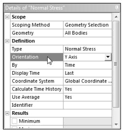
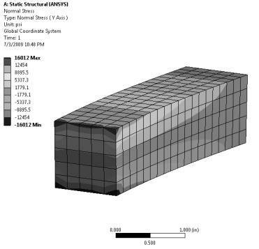
12. Request normal stress. Click on Stress in the toolbar and select Stress-Normal. In the Details pane change the Orientation to Y Axis.
13. Solve. Click on the icon in the toolbar. The solution status window will appear and display the various stages of the solution process. The solution is complete when this window disappears.
14. Once the solution is successfully completed, green check marks will be placed next to the solution quantities you had requested.
15. Save the analysis. From the File menu, select Save Project.
16. Review the results. When the solution is complete, click on one of the solution quantities you requested, such as Directional Deformation or Normal Stress, to display those quantities as
contour plots.

17. Select Contours Bands and Show Elements from the pull down menus. The resulting display is shown below.
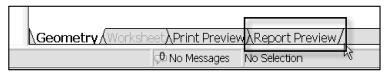
18. Generate a report. A simple HTML report can be automatically generated by simply clicking on the Report Preview tab. The report generated in this way includes basic information about the analysis, such as the type of analysis, material properties of the materials used, boundary conditions, etc.